Sidebar
Table of Contents
Auto Mains Fail Transfer Switch :: ComAp Inteli-ATS
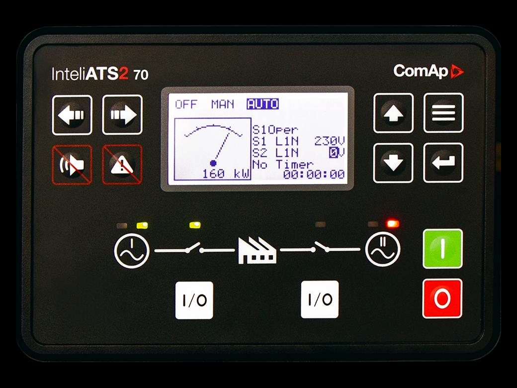 This automatic transfer switch uses a ComAp ATS Controller combined with motor contactor switching to provide a fully-featured ATS with full metering & history logging, and can also be remotely monitored.
- InteliATS 70 adds PLC logic blocks
Motor Contactor Selection
The appropriate size of motor contactors should be selected based on the load served and the genset size. The 400A frame is a good general purpose selection, but smaller or larger can substituted. Recommended source: FactoryMation.com (225A frame and larger have 100-240VAC/DC coils)
- See the discussion at ATS Pro & Con for reasons why this may or may not be an appropriate choice for your application.
See warnings below
One-Line Diagram
![]()
Auto Mains Fail Transfer Switch
One-line diagram, detailed schematic/wiring diagram, and parts list:
(DSN) files can be edited with TinyCAD.
Description of Operation
Contactors K-U [3] and K-G [5] are mechanically and electrically interlocked to ensure that only one can be closed at a time.
Definitions
- Utility Connected: Two Green indicators (L-U, L-KU)
- Generator Connected: Two Blue Indicators (L-G, L-KG)
- Load Connected: White Indicator(s) (one per phase, if desired)
- K-G [3], K-U [4]: Utility & Generator Power Contactors, 400 Amp 3-pole
Utility Power Failure
- Starting with Utility Power being supplied to the load: Contactor K-U [3] is closed, and all timers have expired.
- Power is removed from the coil for K-U [3] if:
- Utility power fails
- Voltage on any phase exceeds minimum or maximum voltage setpoint.
- Frequency exceeds minimum or maximum setpoint
- Phase rotation is reversed
- When K-U [3] opens:
- Load is disconnected (Preventing damage to equipment caused by low voltage.)
- If utility power fails to return within 5 seconds:
- InteliATS closes KGS [6] to start the genset
- Once the generator is running, the InteliATS:
- Qualifies input for minimum, maximum voltage on all phases, correct phase rotation, minimum, maximum frequency
- Illuminates L-G (Blue) indicating generator power is OK.
- Begins countdown (5 seconds).
- K-G [5] then closes:
- Supplies generator power to the load
- Opens the neutral connection for the coil on K-U [3], preventing K-U [3] from closing by accident.
- Illuminates L-KG (Blue) indicating that generator is supplying the load.
Utility Power Return
- When Utility Power returns, InteliATS:
- Qualifies input for minimum, maximum voltage on all phases, correct phase rotation, minimum, maximum frequency
- Indicator L-U (Green) illuminates to confirm utility grid voltage is acceptable
- Begins time delay (15 minutes), which ensures:
- The utility grid has time to stabilize
- Delays adding loads to the grid after an outage
- Eliminates short-cycling if the grid drops again shortly after returning
- Provides a minimum run-time for the generator to ensure it gets up to operating temperature
- Opens the coil for K-G [5]:
- Disconnects load from Generator
- Connects neutral of K-U [3] coil
- K-U [3] closes after setpoint time-delay (as short as 1mS)
- Connects load to Utility Grid
- Disables K-G [5] by disconnecting neutral of coil
- Illuminates L-KU (Green), indicating Utility/Grid is supplying load
- Begins time delay (2 minutes) for Generator cool-down (running with no load)
- Opens KGS [6] to disconnect the generator auto-start signal
- Genset stops
Force Generator Operation
- Operating S2, Auto/Gen, to the “Gen” position forces selection of Generator by InteliATS
- InteliATS will start generator, qualify power, then turn off K-U [3] and turn on K-G [5] after setpoint delay (as short as 1mS).
- Switching S2 back to Auto will switch back to Utility power if it is qualified based on normal setpoint limits.
Manual Bypass
Voltage, frequency, and phase monitoring is inactive while either bypass mode is active!
- Operating S3, Manual Bypass, forces selection of Utility or Generator power and bypasses InteliATS controls, switching InteliATS to “OFF” Mode.
- S4 is a 3-position center return selector switch with “ON” and “OFF”.
- S4 is only enabled when S3 is not in “AUTO”.
- When S3 is in either “City” or “Gen” bypass mode, S4 switches ON or OFF the respective contactor.
- S3 is mounted inside a protective shroud to prevent casual operation.
- Placing S3 in the City (Utility) disables genset auto-start and K-GC (5)
- To turn on City/Utility power, momentarily turn S4 to the “ON” position.
- To turn off the City/Utility Power, momentarily turn S4 to the “OFF” position.
- Low voltage from City power will not open contactor K-UC (3) until the voltage falls to approximately 60VAC.
- Placing S3 in the Generator position disables K-UC (3), City Power and starts the Generator.
- To switch on Generator power, momentarily turn S4 to the “ON” position once generator is up to speed.
- To turn off the Generator Power, momentarily turn S4 to the “OFF” position.
- Power to the load will remain OFF until S3 is returned to AUTO, or switched to CITY.
- If the generator fails (or runs out of fuel) and the voltage falls below approximately 60VAC, contactor K-UG (5) will open by itself.
- Allowing this to happen can damage equipment, including the generator diodes.
Emergency Stop
- Operating the Emergency Stop (E-Stop) mushroom switch immediately disconnects all power sources and shuts down genset, if it is operating.
- The E-Stop must be turned clockwise to release the latched condition, and the alarm reset on the InteliATS in order to return to normal operation.
Bill of Materials
[Incomplete, work in progress]
117 ATS -- Automatic Transfer Switch-Contactor
:: WARNING ::
Follow all applicable electrical codes. Consult a licensed electrician or an electrical engineer for assistance selecting appropriate wire size, circuit breaker, and contactor ratings. These plans assume that you have the necessary expertise and experience, or that you will consult with and work under the supervision of a licensed electrician or experienced electrical engineer, for assembly and implementation. Failure to do so can result in serious personal injury, damage to property, destruction of generator sets and wiring, even causing fires and death.
DANGER: Current transformers must be connected to a device, or short-circuited before power is applied in the circuit to be measured. Current transformers are constant current devices, not constant voltage like ordinary transformers.
- A C.T. with loose leads can have lethal voltage on the terminal, possibly over 1000V.
- Do not disconnect a C.T. when power is present in the measured circuit!
Page Tools

Copyright © Alan Shea, 2011-2026