Sidebar
Table of Contents
Auto Mains Fail Transfer Switch :: Relay Logic
This Auto Mains Fail or Automatic Transfer Switch uses "Relay Logic" to control two motor contactors (rated 100A or above) to transfer power to a load circuit between utility power and a standby generator.
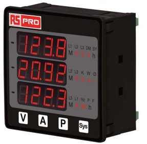 One or more multi-meters can be included but are not shown.1)
Motor Contactor Selection
The appropriate size of motor contactors should be selected based on the load served and the genset size. The 400A frame is a good general purpose selection, but smaller or larger can substituted. Recommended source: FactoryMation.com (225A frame and larger have 100-240VAC/DC coils)
- See the discussion at ATS Pro & Con for reasons why this may or may not be an appropriate choice for your application.
See warnings below
One-Line Diagram
![]()
Auto Mains Fail Transfer Switch -- Selector Switch
One-line diagram, detailed schematic/wiring diagram, and parts list:
(.dsn) files can be edited with TinyCAD.
Description of Operation
Contactors K-U [13] and K-G [14] are mechanically and electrically interlocked to ensure that only one can be closed at a time.
Definitions
- Utility Connected: Two Green indicators (L-U, L-KU)
- Generator Connected: Two Blue Indicators (L-G, L-KG)
- Load Connected: White Indicator(s) (one per phase, if desired)
- K-G [13], K-U [14]: Utility & Generator Power Contactors, 400 Amp 3-pole
- K-PHM-U [2], K-PHM-G [10] : Phase Monitor – Loss of phase, phase rotation, and low voltage relay
- K-VM-UA [3], K-VM-GA [9] : Over voltage relay
- K-US [4], K-GS [8] : Time Delay (Voltage stabilization)
- K-U ENABLE [5] : Time delay to ensure utility/grid power stability & minimum generator run-time
- K-G STOP [6] : Generator cool-down delay
- K-G START [7] : Generator start delay after utility power failure
Utility Power Failure
- Starting with Utility Power being supplied to the load: Contactor K-U [13] is closed, and all timers have expired.2) Timer K-G STOP [6] has expired and its contacts are closed.
- Power is removed from the coil for K-U [13] if:
- Utility power fails
- A phase is lost or the voltage drops below the limit set by K-PHM-U [2]
- Voltage goes above the limit set by K-VM-UA [3]
- When K-U [13] opens:
- Load is disconnected (Preventing damage to equipment caused by low voltage.)
- Removes power from timer K-G START [7], which starts its timer.
- If Utility/Grid returns before K-GS [8] time delay closes K-G [14]:
- K-U [13] will close after K-US [4] delay
- K-G STOP [6] will time out, potentially running the genset for up to K-G STOP [6] time delay.
- When timer K-G START [7] expires (30 seconds), its contacts close, which causes the selected genset to begin its autostart sequence.
- Once the generator is supplying power:
- K-PHM-G [10] qualifies all phases live, phase rotation, and minimum voltage
- K-VM-GA [9] qualifies maximum voltage
- Illuminates L-G (Blue) indicating generator power is OK.
- K-GS [8] begins its countdown (30 seconds).
- K-G [14] then closes:
- Supplies generator power to the load
- Opens the neutral connection for the coil on K-U [13], preventing K-U [13] from closing by accident.
- Illuminates L-KG (Blue) indicating that generator is supplying the load.
Utility Power Return
- When Utility Power returns, it must meet the constraints:
- K-PHM-U [2] for phase (all phases live, correct phase rotation) and minimum voltage
- K-VM-UA [3] maximum voltage
- Indicator L-U (Green) illuminates to confirm utility grid voltage is acceptable
- K-US [4] begins voltage stabilization delay (10 seconds).
- K-U ENABLE [5] begins time delay (15 minutes), which ensures:
- The utility grid has time to stabilize
- Delays adding loads to the grid after an outage
- Eliminates short-cycling if the grid drops again shortly after returning
- Provides a minimum run-time for the generator to ensure it gets up to temperature
- When K-U ENABLE [5] turns on, it opens the coil for K-G [14]:
- Disconnects load from Generator
- Connects neutral of K-U [13] coil
- K-U [13] closes immediately
- Connects load to Utility Grid
- Disables K-G [14] by disconnecting neutral of coil
- Illuminates L-KU (Green), indicating Utility/Grid is supplying load
- Provides power to K-G STOP [6]
- K-G STOP [6] begins time delay (2 minutes) for Generator cool-down (running with no load)
- K-G START [7] turns on, disconnecting the generator auto-start signal
- Genset stops
Bill of Materials
116 ATS -- Automatic Transfer Switch-Contactor
:: WARNING ::
Follow all applicable electrical codes. Consult a licensed electrician or an electrical engineer for assistance selecting appropriate wire size, circuit breaker, and contactor ratings. These plans assume that you have the necessary expertise and experience, or that you will consult with and work under the supervision of a licensed electrician or experienced electrical engineer, for assembly and implementation. Failure to do so can result in serious personal injury, damage to property, destruction of generator sets and wiring, even causing fires and death.
Page Tools

Copyright © Alan Shea, 2011-2026